

SAFETY:
Please take proper safety precautions when dealing with electronics and soldering. Have proper ventilation and a clean work area. Research basic soldering technique if in doubt. I cannot be held responsible for any damages that could occur to you or your equipment while following the procedures present on this Website.
This page is being overhauled. Some of the pictures are from older RGB AMP revisions. Do not worry. The installation instructions below will work with the current RetroFixes RGB Kit.
Getting Started:
What you need:
- Basic soldering skills!
- The 4.5mm tool that opens the SNES (available in the store)
- Philips head screwdriver.
- Soldering iron & solder.
- Wire Strippers
- Small piece of electrical tape.
- Small wire snipers.
Read this Awesome "Soldering is Easy – Comic" for Basic 101s of soldering click here.

RGB Kit Amp Pads & Jumpers
R=Red
G=Green
B=Blue
Y= Luma
C= Chroma
CS=CSNYC
TTL Sync Jumper:
This jumper will set the sync type. My kit will ship with the Jumper "open" and is attenuated for 75 ohm Csync.
If your cable attenuates TTL C-Sync to 75Ohm please solder the TTL jumper closed. Shorting the TTL jumper will restore the C-Sync signal back to a TTL logic level.
Before doing anything unplug the consoles & turn the power switch "ON" This will discharge the internal capacitors.
Installation:
Start by removing all 4.5 bit screws from the bottom side of console.

Next Remove all visible screws from the motherboard. Make note of different screws sizes, the larger silver screws secure the game slot and rear multiport. All other screws surround the board.

Now it is time to prep the RetroFixes RGB amp. To insure 100% reliability I prefer adding a piece of electrical tape to the rear of the RGB amp. Do not skip this step! (example photo from different board design)

Locate these areas on bottom of motherboard.

Before placing the RGB kit on the motherboard: Make sure to trim these pins and remove the solder glob (if required)
Note: Some SNES consoles will have two ground pins soldered together. If your console has this extra solder remove it before placing the amp into place. You can either snip the solder away with snipers or remove the solder with a desoldering hand pump

Next, solder the amp to the multiout pins. Simply solder all the 12 pins as shown below.


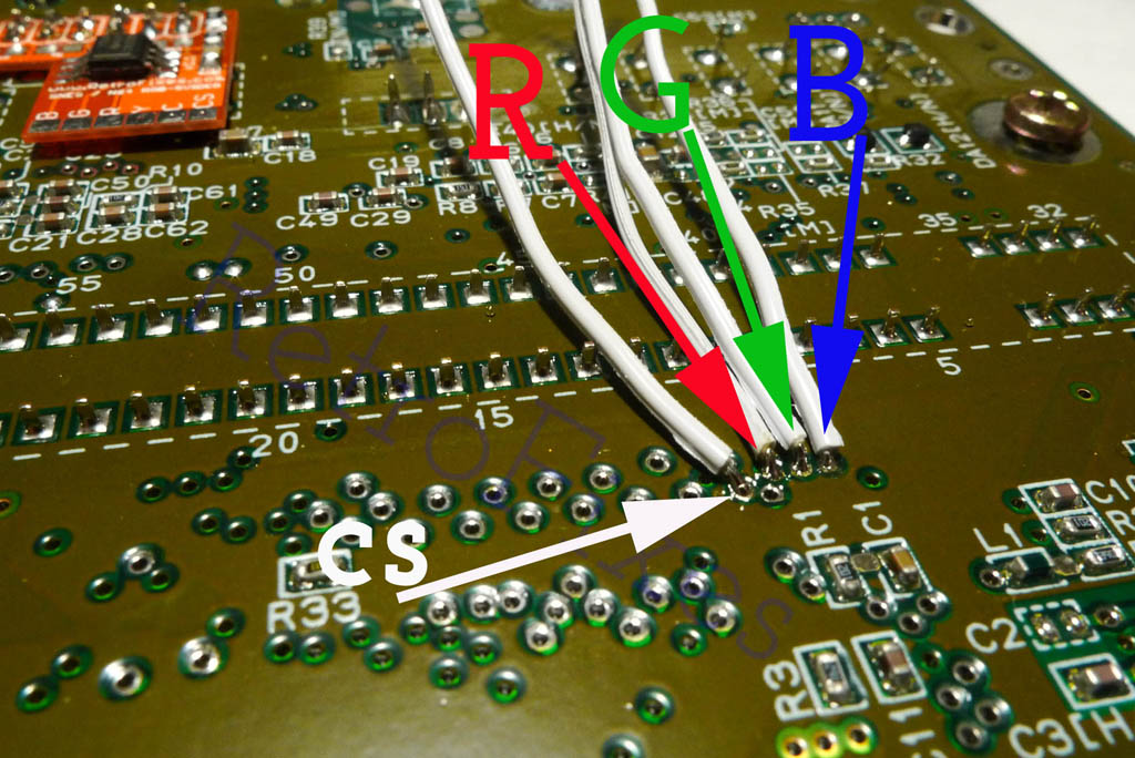
Next, locate this spot on the motherboard:
This location is very important, study it closely before soldering. CS, Red , Green, Blue are found here.

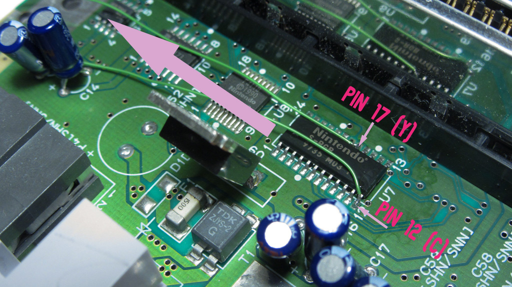
For Svideo install: (C & Y Pads)
Locate the SNES "S-RGB" chip located on top near the Heat-shield. Removing the Heat-shield is necessary and it is held down with 3 screws.

Locate IC Pins 12, 17 & on the chip. Use the photo as a guide.
Pin17 = Y (luma)
Pin 12 = C (chroma)
Make sure to guide your wires to the left side (shortest path) and wrap around and under to the RGB amp. Caution: When reinstalling the heatshield do not crush your wires.
Solder your 2 wires to the Y & C pads on the SNES AMP.
That's the basics of installing RGB amps. Make sure to reassemble the heatshield & RF shielding and all the SNES motherboard screws. Pay careful attention to wire locations and do not crush your wires during assembly.
Test and Enjoy. If you have any issues we are here to help.


