Collection: View Our Entire Catalog
Explore our complete catalog. At RetroFixes, we aim to assist you in expanding your collection. Whether you choose to buy a refurbished gaming console or seek the components necessary for a DIY refurb, we have you covered. From retro computer equipment to DIY music synth kits, we've got everything you need!

-
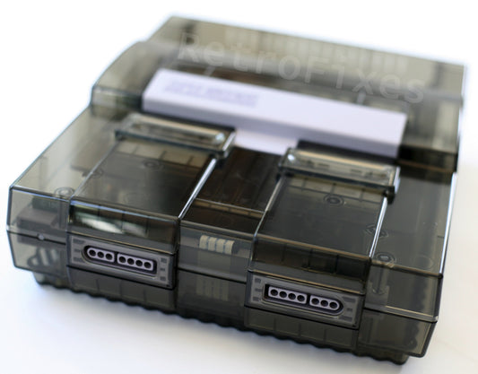
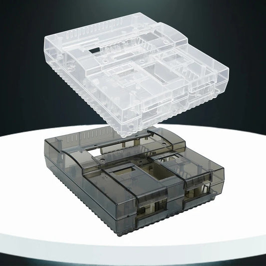
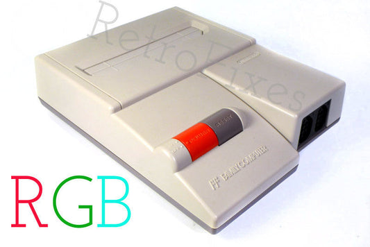
Custom SNES RGB Translucent Smoke Black Console
Regular price $ 350.00 USDRegular priceUnit price per -
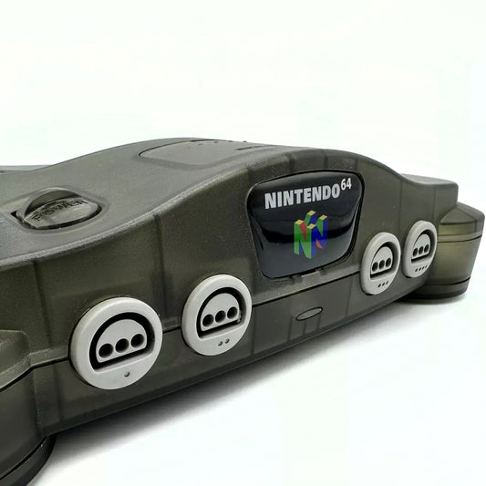
Custom N64 RGB Upgraded Console with Translucent Smoke Shell
Regular price $ 325.00 USDRegular priceUnit price per -
 Sold out
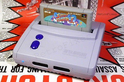
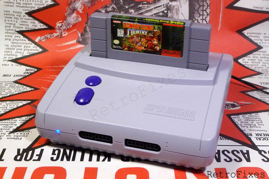
Super Nintendo SNES Jr RGB Console
Regular price $ 300.00 USDRegular priceUnit price per -
 Sold out
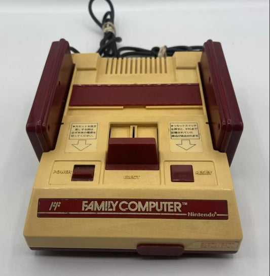
NES & Famicom RGB Upgrade Service.
Regular price From $ 175.00 USDRegular priceUnit price per -
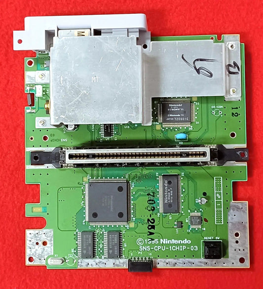
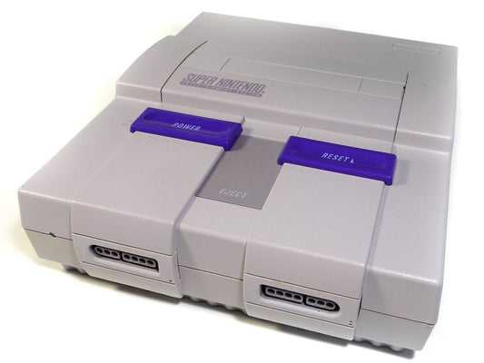
Super Nintendo SNES 1 Chip - 03 Motherboard Replacement
Regular price $ 140.00 USDRegular priceUnit price per -
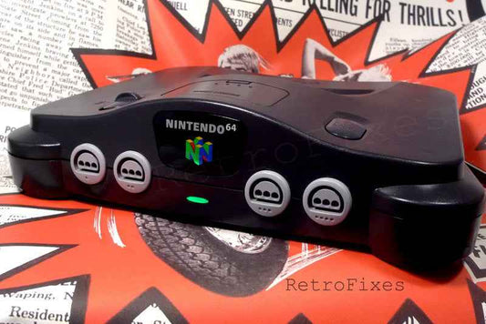
N64 RGB Upgrade Service
Regular price From $ 120.00 USDRegular priceUnit price per -
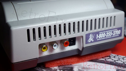
Nintendo NES Toploader Composite Upgrade Service
Regular price $ 120.00 USDRegular priceUnit price per -
Deluxe SNES Jr RGB Video Upgrade Service
Regular price $ 120.00 USDRegular priceUnit price per -
SNES Upgrade RGB Bypass + Vertical Line + Ghosting Fix Service
Regular price From $ 100.00 USDRegular priceUnit price per -
SNES Console Shell Replacement Service
Regular price $ 95.00 USDRegular priceUnit price per -
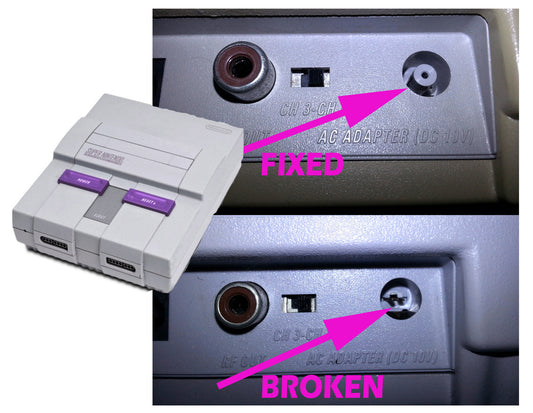
Super Nintendo SNES Power Port Repair
Regular price From $ 88.00 USDRegular priceUnit price per -
 Sold out
Plastic Cleaning Kit
Regular price $ 50.00 USDRegular priceUnit price per -
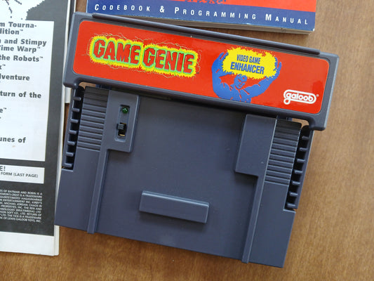
SNES Game Genie complete with original paperwork
Regular price $ 50.00 USDRegular priceUnit price per -
Console Refurbishment Service
Regular price From $ 49.00 USDRegular priceUnit price per -
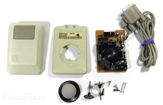
Vintage Macintosh Mouse & Keyboard Repairs. 512k, 1mb & more.
Regular price $ 49.00 USDRegular priceUnit price per -
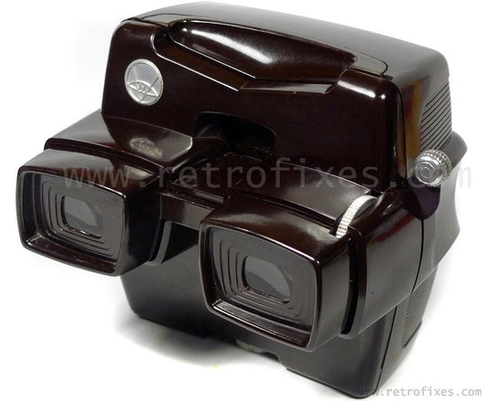
ViewMaster Focusing Model D Restoration & Repair Service
Regular price From $ 49.00 USDRegular priceUnit price per -
SNES SHVC Sound Module Board
Regular price $ 45.00 USDRegular priceUnit price per -
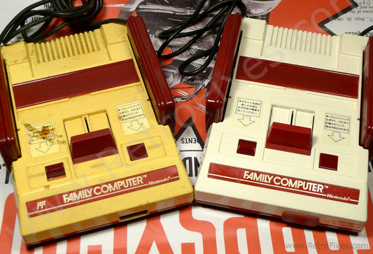
Original Nintendo Famicom Console - Bargain Sale
Regular price $ 45.00 USDRegular priceUnit price per -
 Sold out
NES Toploader Custom Multiout Port
Regular price $ 39.00 USDRegular priceUnit price per -
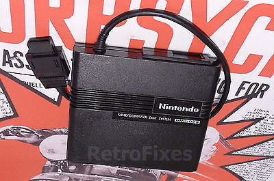
Nintendo Famicom Disk System - RAM Adapter
Regular price $ 39.00 USDRegular priceUnit price per -
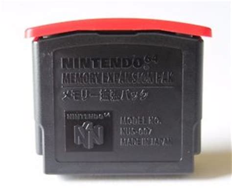
Nintendo 64 Expansion Pack NUS-007 OEM N64 Official
Regular price $ 38.95 USDRegular priceUnit price per -
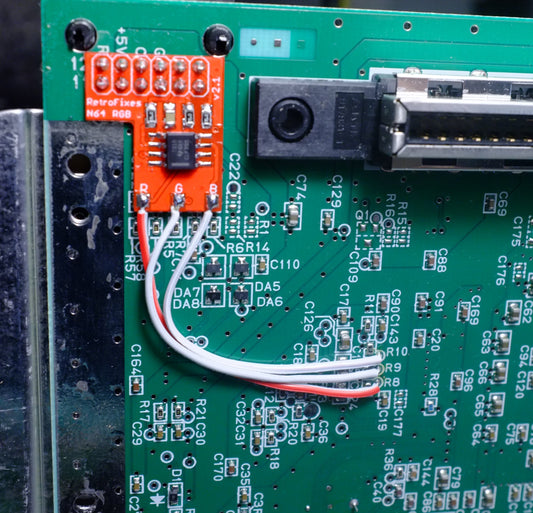
N64 RGB Video Board
Regular price From $ 35.00 USDRegular priceUnit price per -
 Sold out
SNES SPDIF Digital Audio Board
Regular price $ 35.00 USDRegular priceUnit price per -
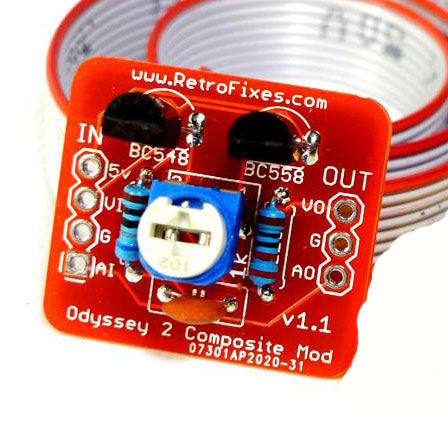
Magnavox Odyssey 2 Composite Video Board
Regular price From $ 35.00 USDRegular priceUnit price per -
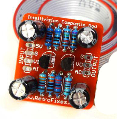
Intellivision Composite Video Board
Regular price From $ 35.00 USDRegular priceUnit price per -
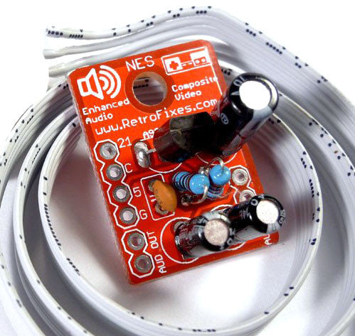
NES-101 Composite Video Board
Regular price From $ 35.00 USDRegular priceUnit price per -
NES Toploader Custom RCA Composite Port
Regular price From $ 35.00 USDRegular priceUnit price per -
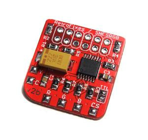
SNES RGB Video Board
Regular price From $ 35.00 USDRegular priceUnit price per -
Colecovision Composite Video Board
Regular price From $ 35.00 USDRegular priceUnit price per -
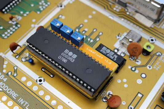
Commodore C64 / 64C JailBar Eliminator LumaFix64 Kit
Regular price $ 29.95 USDRegular priceUnit price per -
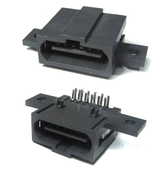
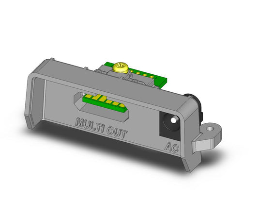
Original Nintendo Multiout Port GC, N64 or SNES versions
Regular price From $ 29.00 USDRegular priceUnit price per -
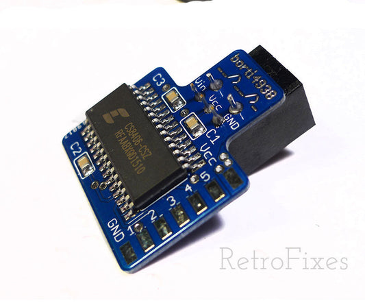
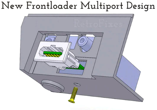 Sold out
NES Frontloader Multiout Port
Regular price $ 29.00 USDRegular priceUnit price per -
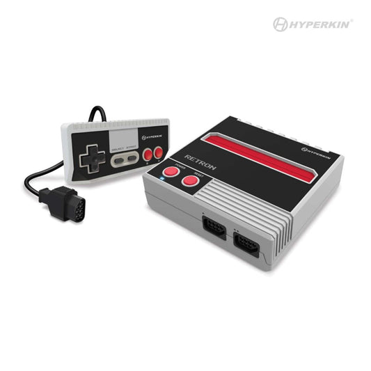 Sold out
NES RetroN 1 AV Gaming Console
Regular price $ 29.00 USDRegular priceUnit price per -
Famicom to NES Game Adapter Expansion Audio Enabled 60 to 72 Pin Convertor
Regular price $ 28.00 USDRegular priceUnit price per -
LM1881 Sync Stripper-in-SCART Board
Regular price $ 26.00 USDRegular priceUnit price per -
 Sold out
Retro Computer Brick Set 228pcs
Regular price $ 25.00 USDRegular priceUnit price per